Introduction to the Research Lab:
Laboratory Equipment
By Dina Constantinides and Sarah Bordenstein, Penn State University
This page features interactive Discovery Tools. Click on the highlighted text preceding the Discovery icon ![]() to view supporting videos.
to view supporting videos.

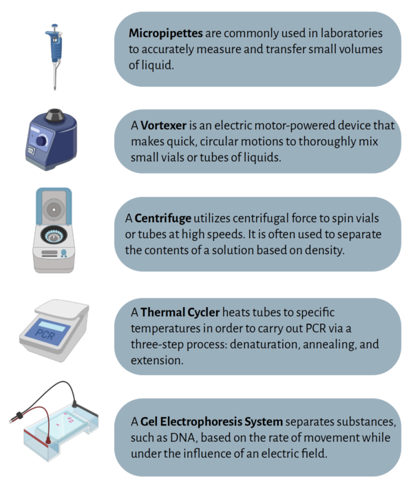
MICROPIPETTES
Introduction
Pipettes are commonly used in laboratories to accurately measure and transfer a desired volume of liquid. The prefix micro- comes from the Greek word for “small” and is abbreviated as “μ”. A micropipette is different from a regular pipette in that it specifically measures and transfers small volumes of liquid from 0.1 μl up to 1,000 μl (or 1 ml). In this lab series, we will use the term “micropipette” interchangeably with “pipette” to refer to this device.
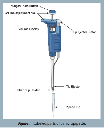
Before jumping into the lab exercises, familiarize yourself with the parts of a micropipette and review its proper use. Figure 1 labels the parts of a common micropipette. Some pipettes may differ slightly from this illustration.
Getting Started
Follow the seven steps ![]() outlined below for a detailed tutorial on how to use a micropipette.
outlined below for a detailed tutorial on how to use a micropipette.
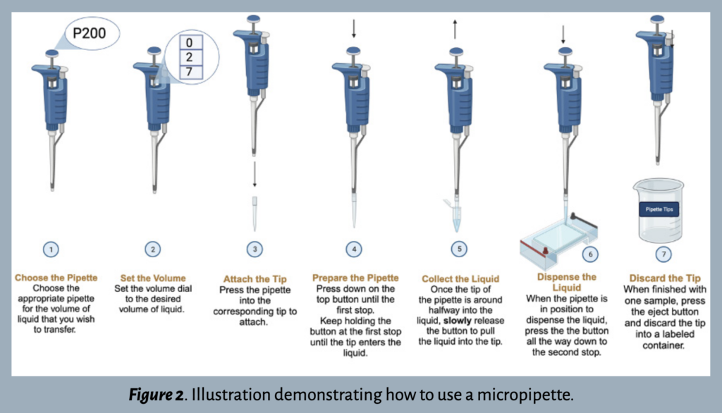
Step 1: Choose the pipette.
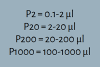
After familiarizing yourself with the various parts of a micropipette, determine which pipette is best suited for your experimental needs. There are typically four options within a laboratory: P2, P20, P200, or P1000. Each number refers to the maximum volume of liquid – in microliters (μl) – that the pipette can measure. The volume range is printed on the side of the pipette and/or on the plunger button.
The most accurate measurement is made using the smallest pipette within the recommended range. For example, the P20 pipet would be the best option to measure 13.5μl of liquid because it is more than 2μl but less than 20μl.
Step 2: Set the volume  .
.
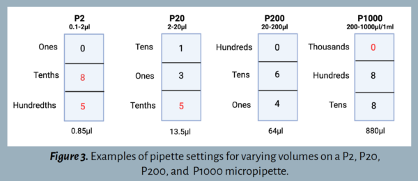
It’s important to understand how to set the volume dial correctly. Each pipette has a three-digit volume window to accommodate the largest indicated volume (see Figure 3).
- P2: The largest volume is 2 μl. The top digit represents the ones position, the middle digit represents tenths, and the bottom digit represents hundredths.
- P20: The largest volume is 20 μl. The top digit represents the tens position, the middle digit represents ones, and the bottom digit represents tenths.
- P200: The largest volume is 200 μl. The top digit represents the hundreds position, the middle digit represents tens, and the bottom digit represents ones.
- P1000: The largest volume is 1000 μl. The top digit represents the thousands position, the middle digit represents hundreds, and the bottom digit represents tens.
The number on the display is adjusted by turning the volume adjustment dial in either direction. Many pipettes have a lock located below the plunger button that must be switched to the unlock position while changing the number. Ensure that it is locked when pipetting.
Step 3: Attach the tip .
Each pipette requires a corresponding box of tips with the same volume range, as listed on the box. While most pipettes are compatible with universal tips, some brands require specialized tips. Once the correct tips have been selected, open the lid and press the end of the pipette into one of the tips. Press firmly enough to make a tight connection without breaking the plastic.
Step 4: Prepare the pipette .
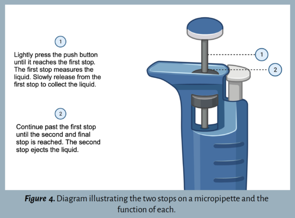
Press the plunger button down until there is resistance – this is the first stop out of two (Figure 4). Continue holding the button down at the first stop and insert the pipette into the liquid.
Step 5: Collect the liquid .
Once the tip is about halfway into the liquid, slowly release the plunger button to pull the liquid into the pipette tip. Be sure that the tip is always submerged when pulling in the liquid. To avoid cross-contamination of samples, do not allow any other parts of the pipette to make contact with the liquid.
Step 6: Dispense the liquid .
When ready to release the liquid, slowly press down the plunger button to the second and final stop (Figure 4).
Step 7: Discard the tip .
After the liquid has been transferred, press the tip ejector button (see Figure 1) and dispose of the tip in a labeled waste cup. It’s important to use a new tip for each sample to avoid cross-contamination. Later, the tips should be disposed of in a designated waste disposal area.
Helpful Tips
- Try to keep the lid to the box of tips closed when not in use. This will prevent contamination of the tips for future use.
- If in doubt that the correct volume was transferred, get a new tube, and repeat the steps. If this is not possible, make a note of the potential mistake in your lab notebook.
- It is normal to occasionally have an air bubble in the pipette tip. However, this may affect the accuracy of the measurement. If an air bubble is present inside the pipette tip, empty all liquid back into the container and try again.
- Pipetting too quickly can result in the liquid jumping into the top of the tip and may contaminate the micropipette shaft.
Proceed to the Worksheets & Lab Activities Below
Illustrations made with BioRender.
VORTEX MIXER
Introduction
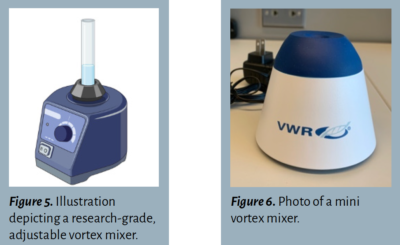
Another tool commonly used in laboratories is a vortexer, or vortex mixer. This electric device makes quick, circular motions to thoroughly mix small vials or tubes of liquids. When used correctly, a vortex will be visible ![]() inside of the tube. Vortex mixers are made in different shapes and sizes. An adjustable, research-grade vortexer is illustrated in Figure 5. Another common option is a mini vortex mixer, shown in Figure 6.
inside of the tube. Vortex mixers are made in different shapes and sizes. An adjustable, research-grade vortexer is illustrated in Figure 5. Another common option is a mini vortex mixer, shown in Figure 6.
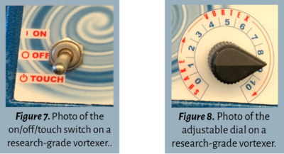
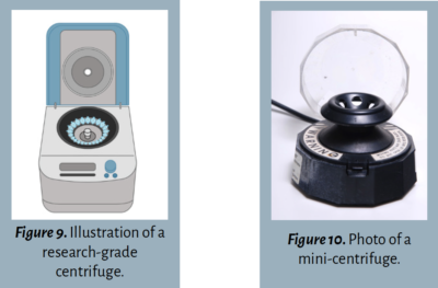
Mini vortex mixers are often touch-based and non-adjustable, operated by pressing the sample tube against the base. For larger vortex mixers, such as the Vortex Genie 2, there are usually two controls ![]() :
:
- On/off switch. This often features “on” or “touch” options (see Figure 7). The “on” feature will automatically turn it on for continuous vortex, while the “touch” feature operates only when the tube or vial is pressed against the base.
- Variable speed control. Some vortex mixers allow users to adjust the intensity. For the purposes of this lab series, set the dial set between 7 and 9 for high-speed mixing (see Figure 8).
Helpful Tips
- Completely seal each tube before using the vortex mixer to avoid spilling the sample and releasing aerosols into the environment.
- With a small number of tubes, it is acceptable to hold the tubes and press them against the base of the vortexer. A tube rack or adapter may be used to vortex multiple tubes at once.
- Make sure there is a visible vortex inside of the tube. If not, reposition the tube(s) on the platform to ensure efficient mixing.
Illustrations made with BioRender.
CENTRIFUGE
Introduction
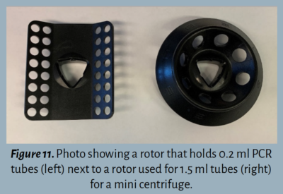
Similar to vortex mixers, centrifuges come in a variety of brands and sizes. Commonly, labs use adjustable centrifuges that hold large numbers of samples (Figure 9). These research-grade centrifuges are set to spin at a defined speed for a given amount of time. The speed, measured in either Relative Centrifugal Force (RCF; x g) or Revolutions Per Minute (RPM), can be ajusted using a dial on the centrifuge. They often feature a lid covering the rotor, which must be removed before loading samples and screwed back on afterwards (particularly if spin columns are being used).
Alternatively, a mini centrifuge (Figure 10), holds a fewer number of tubes and allows for quick and convenient spins. Mini centrifuges often have a pre-determined speed that cannot be adjusted.
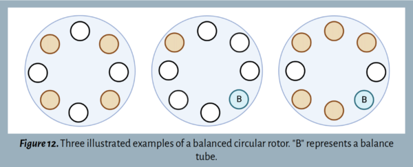
The rotor sits inside of the centrifuge and holds the tubes. Rotors are replaceable ![]() and come in different sizes to accommodate various sizes of sample tubes. For example, a different rotor is needed to spin 0.2 ml PCR tubes as opposed to 1.5 ml tubes.
and come in different sizes to accommodate various sizes of sample tubes. For example, a different rotor is needed to spin 0.2 ml PCR tubes as opposed to 1.5 ml tubes.
The rotor must be balanced before turning on the centrifuge to ensure that it functions correctly. If the rotor is not balanced, the center of gravity will be off, causing a loud sound and potential damage to the equipment.
When loading tubes into the rotor, orient them in opposite positions ![]() . With an odd number of tubes, a balance tube (B) can be made using water filled to the same volume as the other tubes. See Figure 12 and Figure 13 for examples of balanced centrifuge rotors.
. With an odd number of tubes, a balance tube (B) can be made using water filled to the same volume as the other tubes. See Figure 12 and Figure 13 for examples of balanced centrifuge rotors.

Helpful Tips
- Ensure that the lids are tightly sealed before centrifugation.
- There can be multiple ways to correctly balance a rotor.
Proceed to the Worksheets & Lab Activities Below
Illustrations made with BioRender.
THERMAL CYCLER
Introduction
A Thermal Cycler, otherwise known as a PCR machine, is most commonly used to amplify sections of DNA via polymerase chain reaction (PCR). To read more about PCR and its applications, see Lab 3 of the Wolbachia Project.
Thermal cyclers do exactly what their name implies; they fluctuate the temperature of samples over a given number of cycles. The temperature fluctuations allow for denaturation of the DNA, annealing of the PCR primer, and extension of the primer to the end of the amplicon. In general, PCR programs are based on the melting temperature (Tm) of the primers and length of DNA being amplified.
Thermal cyclers can also be used as incubators, as they can be programmed to hold samples at one temperature for a given amount of time. Often, the thermal cycler is programmed to hold DNA samples at 4C indefinitely (∞) after the run is complete to ensure preservation of the sample until it is removed from the machine. A thermal cycler can also be used for enzymatic assays when a sample must be incubated at precise temperatures.
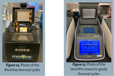
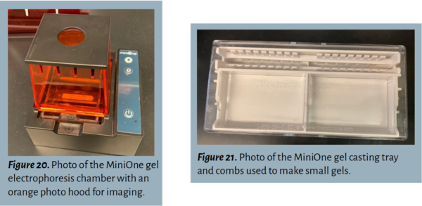
The operation instructions for a thermal cycler vary depending on the model and size. Mini thermal cyclers, such as MiniOne (shown in Figure 14) and miniPCR, hold smaller numbers of tubes and are programmable with a mobile device. Larger thermal cyclers, such as the VeritiPro (shown in Figure 15), are programmed directly on the device, hold a greater number of tubes, and provide numerous customizable options.
Helpful Tips
- Thermal cyclers typically hold smaller tubes designed specifically for PCR. Be sure that your samples are in the correct tubes and lids are tightly sealed to prevent evaporation.
- Some thermal cyclers require adapters when using tubes rather than plates. Failing to use the adapters may result in melted tubes.
- Double check the program that you are running before starting the thermal cycler. If required, enter the correct sample volume (the total volume of liquid inside each tube).
- For PCR, make sure that your thermal cycler is set to hold samples at 4C after the program is complete.
- With some PCR machines, you can view the temperature fluctuate in real time as the cycle runs.
GEL ELECTROPHORESIS
Introduction
Gel Electrophoresis is a technique that has been used for decades by scientists to separate, identify, and quantify DNA, RNA, or protein fragments. After DNA fragments have been amplified by PCR, for example, an agarose gel electrophoresis system is used to verify the presence and quantity of DNA in the sample.
The agarose gel electrophoresis system works by applying an electric current to an agarose gel with wells for each sample to be inserted. Because DNA is negatively charged, it will naturally move towards the positive end of the gel when the current is applied. The agarose gel, surrounded by a buffer solution, serves as a thick, porous material that slows the movement of DNA so that it can be observed.
Differently sized DNA fragments move at different speeds through a gel; smaller fragments move more quickly to the bottom of the gel while larger fragments move more slowly. This difference in movement speed allows fragments to be separated by size. Fragments of the same size will move at the same speed and clump together, forming a band in the gel. A DNA ladder containing DNA fragments of known sizes is loaded into one of the wells and serves as a visual reference to estimate the size of each band. The presence or absence of a band of a known size informs the researcher if the fragment that they are looking for is amplified. If no bands are present, either the specific DNA fragment is not present in the sample or something went wrong earlier in the experiment. For more explanation about this process, see the materials for Lab 4 of The Wolbachia Project.
Like most lab equipment, agarose gel electrophoresis systems are available in different sizes and from different manufacturers. Systems vary in the number of samples that they can hold, the presence/absence of an integrated power supply, and the presence/absence of an integrated transilluminator. This guide will review the components of a standard agarose electrophoresis system as well as the MiniOne gel electrophoresis system.
Getting Started
This guide covers two electrophoresis systems:
- Standard Gel Electrophoresis System
- MiniOne Electrophoresis System
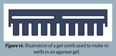
This system is most common in research laboratories and consists of a gel electrophoresis chamber, external power supply, gel casting tray, gel combs, and external imager.
Step 1: Prepare the agarose solution .
Create an agarose solution by dissolving agarose powder in a buffer according to the instructions of the system. Allow the heated solution to sit for a few minutes before pouring.
Step 2: Prepare the casting tray .
Step 3: Pour the gel .
Pour the agarose gel solution into the casting tray and allow the gel to solidify for around 1 hour. Ensure that liquid is not leaking out of the tray.
Step 4: Assemble the electrophoresis chamber .
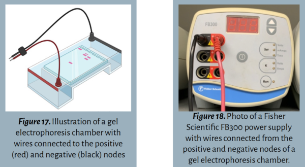
Step 5: Add the running buffer .
Before loading samples into the wells, add a buffer solution to the chamber up to the fill line to help conduct the current through the gel. Commonly used buffers are TAE buffer, TBE buffer, SB buffer, and LB buffer. The buffer added to the chamber should be the same as the one that was used to make the agarose solution in Step 1.
Step 6: Load the gel .
Use a micropipette to add the DNA ladder and samples to the gel. Using a new pipette tip for each sample, carefully hover the tip directly above the well (inside of the buffer solution) and slowly eject the sample inside, being careful not to spill it outside of the well. To avoid introducing extra air, do not press the pipette plunger completely down to the second stop. Use caution to not puncture the gel with the pipette tip. It is vital that the tip is changed after loading each sample to avoid cross-contamination.
A loading dye is commonly added to the samples – either in the PCR master mix or directly to the PCR product – so that the samples are easy to see when loading the wells.
Step 7: Run the gel .
After all of the samples are loaded, set the battery to run.
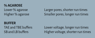
Power supplies are designed specifically for gel electrophoresis and can be set for a specific amount of time at the desired current. Keep in mind that the higher the current (or voltage), the quicker the sample will move through the gel. Voltage and run times are determined by the % agarose and type of buffer used to cast the gel. Higher percentage agarose gels feature smaller pores that allow for slower movement and enhanced discrimination between closely sized fragments relative to lower percentage agarose gels. TAE and TBE buffers require lower voltage which results in longer run times. SB and LB buffers, however, tolerate higher voltage and require shorter run times.
Step 8: Stain the gel .
After the gel has finished running, add a DNA stain in order to visualize bands. Commonly used DNA stains – ethidium bromide, GelRed, GelGreen, and SYBR Safe – vary in sensitivity, toxicity, and price. DNA stains can be added directly to the agarose gel as it is being prepared (pre-cast method) or the gel can be submerged in a stain solution following the gel electrophoresis run (post-stain method). Follow the instructions for the DNA stain available.
Step 9: Visualize the gel .
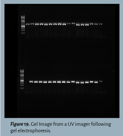
Once staining is complete, the gel is ready to be photographed by an imager that exposes the dye to UV or blue light (depending on the type of DNA stain) to capture the DNA. The final image should show the DNA ladder alongside the loaded samples, with bands present if the desired DNA fragments were amplified during PCR (Figure 19).
Step 1: Prepare the agarose solution .
Microwave the agarose gel solution according to the instructions on the GelCup. Allow the heated solution to sit for a few seconds before pouring.
Step 2: Prepare the casting tray .
Insert the comb(s) into the designated slot on the mini casting tray.
Step 3: Pour the gel .
Pour the agarose solution into the tray and allow the gel to solidify for around 10-20 minutes. Ensure that the gel has fully set, then carefully remove the comb(s) from the gel.
Step 4: Assemble the electrophoresis chamber .
Remove the tray along with the gel and place it inside the gel electrophoresis chamber, ensuring the wells are oriented near the negative end.
Step 5: Add the running buffer .
Locate the running buffer that comes with the GelCups and pour the diluted solution into one end of the chamber until it flows through the other side and up to the fill line.
Step 6: Load the gel .
Load the DNA ladder and samples into the gel using a micropipette. This is done by hovering the tip of the pipette over the well (inside the buffer solution) and carefully ejecting the sample so that it collects inside the well, being careful not to spill it outside of the well. To avoid introducing extra air, do not press the pipette plunger completely down to the second stop. Use caution to not puncture the gel with the pipette tip. It is vital that the tip is changed after loading each sample to avoid cross-contamination.
This system uses the pre-cast method, where a DNA stain (Gel Green) is present in the agarose gel. Therefore, when the blue light is turned on, the user can see the DNA samples as they are loaded into the gel. It is best to use the dim blue light when loading samples (bottom lightbulb button) and save the bright blue light (top lightbulb button) for photographing the gel. This is because the DNA stain is photosensitive and will lose effectiveness after prolonged exposure to blue light.
Step 7: Run the gel .
Once the samples are loaded, use the power button to activate the electric current. Periodically turn on the dim light throughout the run to check if any are bands present and if the DNA is moving through the gel ![]() .
.
Step 8: Visualize the gel .
When enough time has passed, use a mobile device positioned on top of the orange photo hood to capture a photograph of the gel using the bright blue light.
Illustrations made with BioRender.
GLOSSARY
Agarose: A polysaccharide purified from seaweed. When dry agarose is boiled in a buffer solution, it will harden into a flexible, gelatin-like slab as it cools.
Anode: A positively charged electrode.
Balance Tube: A tube that is filled with an equal volume of liquid for the sole purpose of balancing out the centrifuge when spinning an odd number of tubes.
Band: A clearly visible and defined mark on a gel, indicating DNA presence. The location of the band in relation to reference bands in the ladder indicates the size of the DNA product amplified in PCR.
Buffer Solution: A salt-containing solution used in gel electrophoresis to help conduct an electric current through gels.
Cathode: A negatively charged electrode.
Centrifugal Force: Inertial force experienced by objects moving in a circular motion.
Centrifuge: A piece of equipment that utilizes centrifugal force to separate fluids by density.
DNA Ladder: A mix of pre-cut DNA of defined sizes. Each ladder will have different “rungs” of pre-determined sizes; check the product information to find the sizes of DNA for each specific ladder.
DNA Stain: A dye that binds to the DNA, making it visible with UV or blue light.
Electrophoresis Chamber/Box: The box that contains the buffer solution, gel, and positive and negative nodes for gel electrophoresis.
Gel Electrophoresis: A method of separating substances based on the rate of movement while under the influence of an electric field. DNA is often separated and analyzed using agarose gel electrophoresis.
Gel Imager: A device that often uses UV light or blue light to illuminate stained DNA bands in a gel.
Incubator: A machine that holds samples at a constant temperature.
Loading Dye: Loading dye is added to aid in the loading of an agarose gel. It contains colored dye(s), often migrating with specific sizes of DNA, and glycerol.
Micropipette: Tool used to transfer small volumes of liquid (0.1-1000 μl) from one place to another accurately and with minimized possibility for contamination.
Polymerase Chain Reaction (PCR): A common laboratory technique used to amplify DNA fragments. PCR consists of three steps: denaturation, annealing, and extension.
Primer: Approximately 18-30 nucleotides of DNA designed to bind and amplify a specific section of DNA. A PCR reaction contains both forward and reverse primers.
Relative Centrifugal Force (RCF; x g): Unit that describes the gravitational force, or g-force, that is exerted on each sample inside of a centrifuge. This measurement accounts for both the speed of rotation and the distance of the sample from the center of rotation.
Revolutions Per Minute (RPM): Unit that describes the speed at which the rotor revolves.
Rotor: The rotating unit of a centrifuge, the rotor houses the tubes to be centrifuged.
Thermal Cycler: The machine that heats tubes to specific temperatures to carry out PCR and incubations.
Vortexer/Vortex Mixer: Device that thoroughly mixes small vials or tubes of liquids by making quick, circular motions.
WORKSHEETS & LAB ACTIVITIES
Pipette Art Gallery


